Glossary and assumptions
This document contains the basic definitions and assumptions that apply to the rest of content available in this site.
Glossary
Session
User communicates with the available devices in a single session. Session is an abstract object that represents a connection between the client’s programming interface and the devices. The session should be configured before taking any further action. In particular, it is essential to provide a description of the ultrasound system which the user wants to connect to.
During the session, the user can:
get the handle to the available devices (and access e.g. device parameters)
run operations/a graph of operations on the devices (currently available: running a specific sequence operation on the us4R device)
start/stop (freeze) the currently running graph (currently available: starting/stopping the us4R device)
Devices
Device
An abstract class that represents a component of the system. The device can be steered by the user. The device can be programmable, which means that it is possible to load and execute a sequence of operations on the device. Each device and its components are identified by a pair: (device type, ordinal number in the system), e.g. “Us4R:0”, “GPU:0”, “GPU:1”, etc. During a given session the device can be identified by an absolute path to the given device. The absolute path is determined by the device declaration provided in a session configuration file.
Probe
An electronic device that transmits the ultrasound wave and records the response. A probe model is identified by the manufacturer and probe model id, e.g. (“esaote”, “sl1543”) (in future, probe serial number can added).
Devices: us4R and components
us4OEM
An electronic, programmable device responsible for steering the signal transmitted to the ProbeAdapter. Currently, a single us4oem allows to transmit data using 128 channels and acquire echo data using 32 channels in a single Tx/Rx operation.
ProbeAdapter
Probe interface adapter - a system component responsible for the communication between a probe and the system us4OEM modules. The probe interface transfers tx/rx signals between the probe and the selected us4oem modules.
us4R
A complete us4R system. The us4R system consists of: us4OEM modules (e.g. us4R-lite consists of 2 modules, us4R consists of 8 modules), probe adapter, probe, high voltage supplier.
Ultrasound device operations
Scheme
Scheme is a complete program that has to be loaded on the device. Currently, it consists of tx/rx sequence and processing pipeline definitions.
Operation (Op)
In ARRUS, the user defines operations to be executed on a particular device. Each operation has its placement, e.g. TxRx operations can be performed on ultrasound programmable devices (e.g. us4R) and RxBeamforming can be performed on processing units (e.g. CPU or GPU).
TxRx
The ultrasound device implements the TxRx operation, that is, a single transmit and echo signal reception. The result of this operation is stored directly in the system’s DDR memory, and then transferred to the PC for further processing. A single TxRx allows to transmit a signal impulse and receive echo data using at most the number of channels specific for a selected device. A single TxRx operation produces a single RF frame.
TxRxSequence
A sequence of TxRxs to execute on a device in a loop. A single TxRxSequence produces a sequence of frames or a batch of sequences.
Data
RF frame
A frame is an output of a single Tx/Rx operation. An example of a single frame is a 2-D frame which can be beamformed to a single scanline for a linear scanning scheme.
RF sequence
A sequence of frames (in short: sequence) is an output of a sequence of Tx/Rx operations. An example of a sequence is a 3-D array with shape (frame, sample, channel), from which a single b-mode image can be reconstructed.
RF batch
A batch of sequences (in short: a batch) is a collection of multiple RF sequences.
Adopted coordinate system
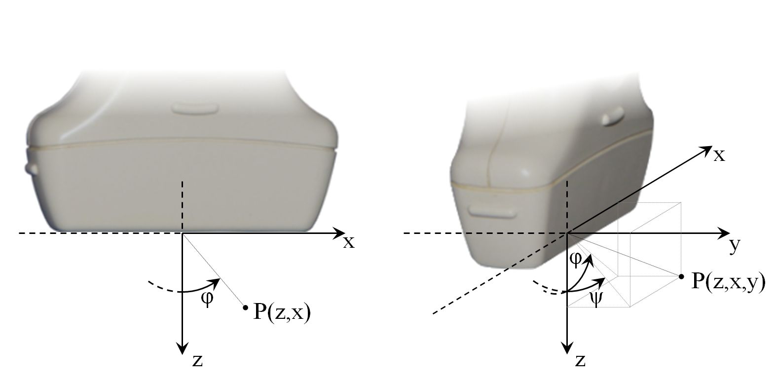
The adopted coordinate system is shown in Fig. 1.

Fig. 1 Adopted coordinate system in the imaging plane (left) and taking into account the 3rd dimension (right).
Important notes:
point coordinates are written in (z,x) or (z,x,y) format
point (0,0,0) is at the center of the probe’s surface,
the orientation of the coordinates’ axes are shown in Fig. 1 ,
angle \(\phi=0\) covers with the z-axis direction and positive \(\phi\) direction is counter-clockwise.