User Guide
This section describes how users can acquire data using ultrasound hardware. Users can communicate with the device via a communication session object. During the session it is possible to upload and run operations.
Configuring session
Note
The below sections contains details on how to configure the provided hardware. You can skip to the section how to run examples if you already have a session configuration file prepared by e.g. us4us developers, and you don’t need to change any device-related parameters.
Session configuration file
A session configuration file consists of device settings valid for a given session. Currently, the configuration file can be written in .prototxt file (a protobuf I/O format readable for humans). Sample configuration files are available here.
Currently only us4R device can be configured using session configuration file.
us4R
To use the us4R system in a particular session, create a field us4r in the
session configuration file.
us4r: {
  # here goes us4r configuration spec.
  hv: {
    # ...
  }
  probe: {
    # ...
  }
  adapter: {
    # ...
  }
}
The us4R device typically includes a high voltage supplier,
which can be configured by providing the hv field. The following power
supplies are currently supported:
the legacy us4R-Lite systems or us4R-lite+ with the external HV: manufacturer:
us4us, name:hv256,us4R-lite+ systems without the external HV: manufacturer:
us4us, name:us4oemhvps,the legacy us4R systems or us4R system with the external HV: manufacturer:
us4us, name:us4rpsc,us4R+ systems without the external HV: manufacturer:
us4us, name:us4oemhvps,us4OEM+ with internal HV: manufacturer:
us4us, name:us4oemhvps.
Example:
hv: {
  model_id {
    manufacturer: "us4us"
    name: "hv256"
  }
}
To turn off the high voltage supplier, skip the hv field.
Based on the HV selected, our software will try to automatically select the type of digital backplane (DBAR) to be used:
for the systems with
hv256power supply,dbarlitewill be used,for the systems with
us4rpscpower supply,us4rpscwill be used,for the systems
us4oemhvps, a system with no digital backplane will be assumed.
It is also possible to explicitly specify the backplane model in the configuration file:
digital_backplane: {
  model_id {
    manufacturer: "us4us"
    name: "model_name"
  }
}
Where model_name can be one of the following: dbarlite or us4rdbar.
To configure us4r’s signal transmission/data reception, it is essential to specify the settings of the probe and probe adapter used in the system.
Specify the settings of the probe and probe adapter
Examples:
Probe Model
The user can specify which probe model they are currently using in one of the following ways:
describe probe model by providing the
probefield, e.g.:
probe: {
  id: {
    manufacturer: "acme"
    name: "my_custom_probe"
  }
  n_elements: 64,
  curvature_radius: 50e-3,
  pitch: 0.21e-3,
  tx_frequency_range: {
    begin: 1e6,
    end: 40e6
  },
  voltage_range: {
    begin: 0,
    end: 100
  }
  lens: {
    thickness: 1e-3,
    speed_of_sound: 2000,
    focus: 20e-3
  }
  matching_layer: {
    thickness: 0.1e-3,
    speed_of_sound: 2100
  }
}
The following probe attributes can be specified:
id: a unique probe model id — a pair:(manufacturer, name),n_elements: number of probe elements,pitch: distance between two adjacent probe elements [m],curvature_radius: radius of probe’s curvature; when omitted and n_elements is a scalar, a linear probe type is assumed [m],tx_frequency_range: acceptable range of center frequencies for this probe [min, max] (a closed interval) [Hz],voltage_range: range of acceptable voltage values, 0.5*Vpp.
Optionally, you can also provide the following attributes:
lens: probe’s lens parameters,matching_layerprobe’s matching layer parameters.
The following lens attributes can be specified:
thickness: lens thickness measured at center of the elevation [m],speed_of_sound: the speed of sound in the lens material [m/s],focus: OPTIONAL, geometric elevation focus in water [m].
The following matching_layer attributes can be specified:
thickness: matching layer thickness [m],speed_of_sound: matching layer speed of sound [m/s].
specify probe model by providing
probe_id:
probe_id: {
  manufacturer: "esaote",
  name: "sl1543"
}
If the latter method is used, the probe model description will be searched in the dictionary file.
When no dictionary file is provided, the Default dictionary will be assumed.
Probe-to-adapter connection
The probe_to_adapter_connection field specifies how the probe elements
map to the adapter channels.
There are several ways to specify this mapping:
channel_mapping- a list of adapter channels to which the subsequent probe channels should be assigned, i.e.channel_mapping[i]is the adapter’s channel to be assigned to probe channelichannel_mapping_ranges- a list of adapter channel regions to which the subsequent probe channels should be assigned.
See here
for an example usage of probe_to_adapter_connection field.
Note:
This field is required only when a custom probe and adapter are specified in
the session configuration file (i.e. probe and adapter fields).
When the probe_id or adapter_id are provided and the connection between
them is already defined, this field can be omitted — the arrus package will
try to determine the probe-adapter mapping based on the dictionary file.
When probe_to_adapter_connection is still given, it will overwrite
the settings from the dictionary file.
Multi-probe systems
It is also possible to specify multiple probes in situations where the system actually has multiple transducers connected. To do this, provide a list of probe definitions, for example:
probe: [
   {
       id: {
           manufacturer: "us4us"
           name: "first_probe"
       }
       n_elements: 64,
       pitch: 0.2e-3,
       tx_frequency_range: {
           begin: 1e6,
           end: 15e6
       },
       voltage_range {
           begin: 0,
           end: 30
       }
   },
   {
       id: {
           manufacturer: "us4us"
           name: "second_probe"
       }
       n_elements: 192,
       pitch: 0.1e-3,
       tx_frequency_range: {
           begin: 1e6,
           end: 15e6
       },
       voltage_range {
           begin: 0,
           end: 30
       }
   }
]
and indicate the probe elements to the system channels mapping, for example:
probe_to_adapter_connection: [
    {
        probe_model_id: {
            manufacturer: "us4us"
            name: "first_probe"
        }
        probe_adapter_model_id: {
            manufacturer: "us4us"
            name: "adapter"
        },
        channel_mapping_ranges: [
        {
            begin: 0
            end: 63
        }],
    },
    {
        probe_model_id: {
            manufacturer: "us4us"
            name: "second_probe"
        }
        probe_adapter_model_id: {
            manufacturer: "us4us"
            name: "adapter"
        },
        channel_mapping_ranges: [
        {
            begin: 64
            end: 255
        }
        ],
    }
]
The order of the probes listed in the probe field affects their identifiers at runtime:
the first probe will have the ID Probe:0, the second Probe:1, and so on.
IO bitstreams and probe external MUXing
It is possible to define IO bitstreams for the purpose of interfacing with external devices e.g.: external MUX to switch probe or probe elements connectivity. In particular, it is possible to define a collection of IO bitstreams to be later used during runtime.
A single bitstream is defined by specifying its states and the duration of each
individual state it consists of using Run-Length Encoding (RLE),
for example in the .prototxt:
bitstreams: [
# bitstream 1
{
  levels: [...]
  periods: [...]
},
# bitstream 2
{
  levels: [...]
  periods: [...]
}
]
The levels field specifies the sequence of “IO levels” to be generated by the device.
IO level is a 4-bit number, where the i-th bit indicates the level of the i-th IO.
The value of periods[i] indicates that the state levels[i] should last for periods[i] + 1 clock cycles (clock 5 MHz).
For example:
bitstreams: [
  {
    levels: [8, 0, 5, 0]
    periods: [0, 1, 4, 0]
  }
]
The above:
sets level 1 on IO 3, level 0 on the remaining IOs, for 0.2 us,
then, sets level 0 on all IOs, for 0.4 us,
then, sets level 1 on IOs 0 and 2, 0 on IOs 1 and 3, for 1 us,
then, sets level 0 on all IOs, for 0.2 us.
Now, it is also possible to specify an IO bitstream that should be triggered before starting TX/RX
for the probe indicated in the TX/RX placement parameter, using the bitstream_id parameter, e.g.:
probe_to_adapter_connection: [
  {
    probe_model_id: {
      manufacturer: "acme"
      name: "probe1"
    }
    probe_adapter_model_id: {
      manufacturer: "us4us"
      name: "adapter"
    },
    channel_mapping_ranges: [
    {
      begin: 192
      end: 255
    }],
    bitstream_id: {ordinal: 1}
  },
  {
    probe_model_id: {
      manufacturer: "acme"
      name: "probe2"
    }
    probe_adapter_model_id: {
      manufacturer: "us4us"
      name: "adapter"
    },
    channel_mapping_ranges: [
    {
      begin: 0
      end: 191
    }],
    bitstream_id: {ordinal: 2}
  }
]
Bitstream numbering (assigning bitstream IDs) starts from 1 (bitstream 0 is reserved for internal purposes).
Using the functionality of configurable IO bitstreams is optional.
Rx Settings
The user can specify the default data reception settings to be set on all system modules. To do this, add an rx_settings with the following attributes:
dtgc_attenuation: digital time gain compensation to apply (given as attenuation value to apply). Available values: 0, 6, 12, 18, 24, 30, 36, 42 [dB]. Optional, no value means turn off DTGC.pga_gain: a gain to apply on a programmable gain amplifier. Available values: 24, 30 [dB]lna_gain: a gain to apply on a low-noise amplifier. Available values: 12, 18, 24 [dB]tgc_samples: a list of tgc curve samples to apply [dB]. Optional, no value/empty list means turn off TGClpf_cutoff: low-pass filter cut-off frequency, available values: 10000000, 15000000, 20000000, 30000000, 35000000, 50000000 [Hz]active_terminationactive termination to apply, available values: 50, 100, 200, 400. Optional, no value means turn off active termination.
Channel masks
To turn off specific channels of the us4R system (i.e. the probe elements),
add the following field to the us4r settings:
channels_mask: a list of system channels that should always be disabled.
TX/RX limits
The .prototxt provides you also the possibility to set constraints (“limits”)
on the TX parameters to be used in run-time.
The default constraints for the transmit pulse length include, among others,
a maximum of 32 cycles of the TX pulse. It is possible to increase the TX pulse length
(for example, to enable imaging methods utilizing long transmit bursts, like SWE)
by setting tx_rx_limits in the .prototxt file.
At the same time, you can restrict some other TX parameters,
such as voltage or PRF (PRI), so as to avoid transmitting a pulse that could be
harmful to the probe, the system, or the target medium.
Example:
tx_rx_limits: {
  voltage: {begin: ..., end: ...}, # [V]
  pulse_length: {begin: ..., end: ...}, # [seconds],
  pri: {begin: ..., end: ...} # [seconds]
}
The interval {begin: …, end: …} defines minimum and the maximum allowable value.
If this TX/RX limits are not provided, default constraints apply.
Watchdog
The us4OEM+ firmware and software implements a host - ultrasound watchdog mechanism.
The purpose of the watchdog is to prevent situations where the OEM board maintains a high HV voltage or continues executing a TX/RX sequence without control from the host PC. The firmware-based OEM watchdog disables HV and trigger when a loss of connection with the host PC is detected. The host PC also detects the lack of response from the device, appropriately notifies the user, and shuts down the entire system.
In some rare cases, some additional watchdog configuration may be needed in order to run the us4R-lite system seamlessly. For example, if the performance of the host PC does not allow for a sufficiently fast response to the OEMs.
You can change the following watchdog parameters:
watchdog: {
    enabled: true
    oem_threshold0: 1.0  # [seconds]
    oem_threshold1: 2.0  # [seconds]
    host_threshold: 3.0  # [seconds]
}
where:
enabled: (bool): whether watchdog should be turned on (true) or off (false), default: true,oem_threshold0: the time after which a “warning” interrupt will be sent to the host PC if the host PC fails to report that it is still alive, default: 1.0,oem_threshold1: the time after which OEM+ will be shut down (stop triggering + turn off HVPS) if the host PC fails to report that it is still alive, default: 1.1,host_threshold: the time after which the host PC will assume that OEM+ is not functioning, if it fails to report that it is still alive, default: 1.0.
You can also turn off the watchdog mechanism by setting the enabled field to false, e.g.:
watchdog: {enabled: false}
HVPS fuse settings
Note
This functionality is available only for OEM+ systems with firmware version
greater than 2.2.0.0.
For systems with the on-board HVPS (us4oemhvps), it is possible to configure
the per-OEM HVPS fuse — i.e. the safety limits on the HVPS output that, when
exceeded, will shut down the high voltage and stop the running TX/RX sequence.
These limits can be specified by adding the hvps_fuse field to the us4r
settings, for example:
hvps_fuse: {
  level1_max_current_threshold:    0.5    # [A]
  level1_max_power_threshold:      1.35   # [W]
  level1_static_voltage_margin:    2.5    # [V]
  level2_max_current_threshold:    0.125  # [A]
  level2_max_power_threshold:      5.0    # [W]
  level2_static_voltage_margin:    2.5    # [V]
}
The level1 and level2 qualifiers correspond to the TX pulse/excitation
amplitude levels — i.e. the amplitude attribute of
arrus::ops::us4r::Pulse (values 1 and 2, see also the 5-level
Waveforms section). For each amplitude level the following thresholds can be
specified:
level<N>_max_current_threshold: maximum allowable HVPS output current generated by a single OEM at amplitude levelN[A],level<N>_max_power_threshold: maximum allowable HVPS output power generated by a single OEM at amplitude levelN[W],level<N>_static_voltage_margin: maximum allowable deviation between the measured HVPS output voltage and the requested voltage at amplitude levelNwhile no TX/RX is running [V].
All fields are optional — any threshold that is omitted keeps its
default value, which is determined at run-time based on the actual hardware
configuration (e.g. HV model, probe voltage range). To rely entirely on the
run-time defaults, simply omit the hvps_fuse field.
Trigger source (TRIG IN/OUT)
By default, us4us systems use an internal trigger source, which runs according to the PRI and SRI settings from the TX/RX sequence. To enable an external trigger source, the following parameter must be set in the configuration file:
external_trigger: true
The trigger output is always enabled by default.
Dictionary
It is possible to specify a dictionary of probe models and adapters that are
supported by the us4R system. To do this, add the dictionary_file field
to the configuration file:
dictionary_file: "dictionary.prototxt"
Currently, the dictionary.prototxt file will be searched in the same
directory where session settings file is located.
When no dictionary file is provided, the Default dictionary is assumed.
An example dictionary is available here: https://github.com/us4useu/arrus/blob/develop/arrus/core/io/test-data/dictionary.prototxt
The dictionary file contains a description of ultrasound probes and adapters that are supported by the us4R device. The file consists of the following fields:
probe_adapter_models: [
  {
    # probe adapter description, the same as described for us4r.adapter field
  },
  {
    # probe adapter description...
  }
]

probe_models: [
  {
    # probe model description, the same as described for us4r.probe field
  },
  {
    # probe model description...
  }
]

probe_to_adapter_connections: [
  {
    # probe to adapter connection, the same as described for us4r.probe_to_adapter_connection field
  },
  {
    # probe to adapter connection...
  }

]
Default dictionary
Arrus package already contains a dictionary files of probes and adapters that
were tested on us4r devices.
To use the default dictionary, omit providing dictionary_file field in your
session configuration file.
Currently, the default dictionary contains definitions of the following probes:
esaote:
probes:
sl1543,al2442,sp2430,ac2541,adapters:
esaote2,esaote3,esaote2-us4r6,esaote3-us4r6
als:
probes:
l14-6aadapters:
esaote2,esaote3
apex:
probes:
tl094adapters:
esaote2,esaote3
ultrasonix:
probes:
l14-5/38,l9-4/38adapters:
ultrasonix,pau_rev1.0
olympus:
probes:
5L128,10l128,5l64,10l32,5l32,225l32adapters:
esaote3
ATL/Philips:
probes:
l7-4,c4-2,adapters:
atl/philips
custom Vermon linear array:
probes:
la/20/128adapters:
atl/philips
custom Vermon matrix array (32x32):
probes:
mat-3dadapters:
3d
Vermon RCA arrays:
probes:
RCA/6/256,RCA/3/64+64adapter:
dlp408r
Running example programs
Example
#include <iostream>
#include <thread>
#include <condition_variable>

#include <arrus/core/api/arrus.h>

int main() noexcept {
    using namespace ::arrus::session;
    using namespace ::arrus::devices;
    using namespace ::arrus::ops::us4r;
    using namespace ::arrus::framework;
    try {
        // Read session configuration from the file.
        auto settings = ::arrus::io::readSessionSettings(
                R"(C:\Users\Public\us4r.prototxt)");
        // Create new session.
        auto session = ::arrus::session::createSession(settings);

        // Get Us4R device handle.
        auto us4r = (::arrus::devices::Us4R *) session->getDevice("/Us4R:0");

        // Tx/Rx sequence:
        // Common Tx parameters:
        ::arrus::BitMask rxAperture(192, true);
        Pulse pulse(4e6, 2, false);

        // Common Rx parameters:
        std::vector<float> delays(192, 0.0f);
        arrus::BitMask txAperture(192, true);
        float pri = 200e-6f;
        ::std::pair<::arrus::uint32, arrus::uint32> sampleRange{0, 2048};
        std::vector<TxRx> txrxs;
        for(int i = 0; i < 10; ++i) {
            txrxs.emplace_back(Tx(txAperture, delays, pulse),
                               Rx(txAperture, sampleRange),
                               200e-6f);
        }
        TxRxSequence seq(txrxs, {}, 500e-3f);

        // Define RF channel data output buffer.
        DataBufferSpec outputBuffer{DataBufferSpec::Type::FIFO, 4};
        // Define scheme to execute.
        Scheme scheme(seq, 2, outputBuffer, Scheme::WorkMode::ASYNC);

        // Upload the scheme.
        auto result = session->upload(scheme);
        // Set HV voltage.
        us4r->setVoltage(10);

        // Create "on new data" callback function.
        // In this example, the callback function counts the number of frames
        // that currently occurred and stops the session when a 10th frame is
        // acquired.
        std::condition_variable cv;
        using namespace std::chrono_literals;
        OnNewDataCallback callback = [&, i = 0](const BufferElement::SharedHandle &ptr) mutable {
            try {
                std::cout << "Iteration: " << i << ", data: " << std::endl;
                std::cout << "- memory ptr: " << std::hex
                                           << ptr->getData().get<short>()
                                           << std::dec << std::endl;
                std::cout << "- size: " << ptr->getSize() << std::endl;
                std::cout << "- shape: (" << ptr->getData().getShape()[0] <<
                                     ", " << ptr->getData().getShape()[1] <<
                                     ")" << std::endl;

                // Stop the system after 10-th frame.
                if(i == 9) {
                    cv.notify_one();
                }
                ptr->release();
                ++i;
            } catch(const std::exception &e) {
                std::cout << "Exception: " << e.what() << std::endl;
                cv.notify_all();
            } catch (...) {
                std::cout << "Unrecognized exception" << std::endl;
                cv.notify_all();
            }
        };

        // Create callback to be called when overflow occurs.
        OnOverflowCallback overflowCallback = [&] () {
            std::cout << "Data overflow occurred!" << std::endl;
            cv.notify_one();
        };

        // Register callbacks in the data buffer.
        auto buffer = std::static_pointer_cast<DataBuffer>(result.getBuffer());
        buffer->registerOnNewDataCallback(callback);
        buffer->registerOnOverflowCallback(overflowCallback);

        // Start the scheme.
        session->startScheme();
        // At this point, data acquisition is started
        // (the occurrence of new data is signaled by the callback function).

        // Wait for callback to signal that the we hit 10-th iteration.
        std::mutex mutex;
        std::unique_lock<std::mutex> lock(mutex);
        cv.wait(lock);

        // Stop the system.
        session->stopScheme();

    } catch(const std::exception &e) {
        std::cerr << e.what() << std::endl;
        return -1;
    }

    return 0;
}
Registering user-defined system interrupt callbacks
In addition to the data-buffer callbacks shown above (OnNewDataCallback,
OnOverflowCallback), ARRUS lets you register callbacks for us4OEM
system interrupts — events such as probe disconnect, watchdog,
TX timeout, pulser interrupt and HVPS fuse. The set of supported
interrupts is defined by the arrus::devices::Us4OEMInterrupt enum
declared in arrus/core/api/devices/us4r/Us4OEMInterrupt.h:
Us4OEMInterrupt::PROBE_NOT_CONNECTEDUs4OEMInterrupt::PULSER_INTERRUPTUs4OEMInterrupt::TX_TIMEOUTUs4OEMInterrupt::WATCHDOG_IRQ0Us4OEMInterrupt::WATCHDOG_IRQ1Us4OEMInterrupt::HVPS_FUSE
System callbacks must be supplied at session construction time — they
are passed to the Us4R device constructor through Us4RSettings. The
callback type is arrus::devices::Us4OEMInterruptCallback
(std::function<void(arrus::devices::Ordinal oem)>) and they are stored
in an arrus::devices::Us4OEMInterruptCallbacksMap keyed by the
Us4OEMInterrupt value.
The recommended way to attach callbacks to a Us4RSettings loaded from
a .prototxt file is to use arrus::devices::Us4RSettingsBuilder:
initialize the builder with the loaded settings, call
setInterruptCallback(interrupt, callback) for every interrupt you want
to handle, then call build().
#include <arrus/core/api/arrus.h>
#include <arrus/core/api/devices/us4r/Us4OEMInterrupt.h>
#include <arrus/core/api/devices/us4r/Us4RSettings.h>
#include <iostream>

using namespace ::arrus::devices;
using namespace ::arrus::session;

// Load the settings from prototxt, attach the system callbacks via the
// builder, and rebuild a SessionSettings holding the modified Us4RSettings.
SessionSettings makeSettings(const std::string &cfgPath) {
    auto loaded = ::arrus::io::readSessionSettings(cfgPath);

    Us4OEMInterruptCallback onWatchdog0 = [](Ordinal oem) {
        std::cout << "WATCHDOG_IRQ0 raised on OEM " << oem << std::endl;
    };
    Us4OEMInterruptCallback onHvpsFuse = [](Ordinal oem) {
        std::cout << "HVPS_FUSE raised on OEM " << oem
                  << " -- entering safe state" << std::endl;
    };

    Us4RSettings modifiedUs4r = Us4RSettingsBuilder(loaded.getUs4RSettings())
        .setInterruptCallback(Us4OEMInterrupt::WATCHDOG_IRQ0, onWatchdog0)
        .setInterruptCallback(Us4OEMInterrupt::HVPS_FUSE,     onHvpsFuse)
        .build();

    return SessionSettings(modifiedUs4r);
}

int main() {
    auto session = createSession(makeSettings(R"(C:\Users\Public\us4r.prototxt)"));
    // ... upload scheme, start scheme, etc.
    return 0;
}
If you want a single function to handle every supported interrupt, the builder offers a convenience method:
auto onAny = [](Us4OEMInterrupt irq, Ordinal oem) {
    std::cout << "Interrupt " << static_cast<int>(irq)
              << " raised on OEM " << oem << std::endl;
};

auto us4r = Us4RSettingsBuilder(loaded.getUs4RSettings())
    .setInterruptCallbackForAll(onAny)
    .build();
You can also iterate over arrus::devices::SAFE_STATE_INTERRUPTS
(std::array of every supported interrupt except WATCHDOG_IRQ0 —
i.e. the ones that mean “stop now”):
Us4OEMInterruptCallback onSafeState = [](Ordinal oem) {
    // bring your application into a safe state...
};
Us4RSettingsBuilder builder(loaded.getUs4RSettings());
for (auto irq : SAFE_STATE_INTERRUPTS) {
    builder.setInterruptCallback(irq, onSafeState);
}
auto us4r = builder.build();
Note
User callbacks are dispatched asynchronously from a dedicated worker thread inside the us4r-api runtime, so a slow callback does not block the underlying us4OEM interrupt dispatcher. Default callbacks (e.g. the watchdog reset) always run first and synchronously, so housekeeping is never delayed by user code. Pending callbacks are discarded on session shutdown.
Custom TX waveforms
Note
Custom TX waveforms are available only for the OEM+ systems.
It is possible to specify arbitrary waveforms using
arrus::ops::us4r::Waveform, arrus::ops::us4r::WaveformSegment
arrus.ops.us4r.WaveformBuilder
classes. See also arrus/core/api/ops/us4r/Waveform.h header file.
Conceptually, WaveformSegment is one particular fragment of a Waveform:
it is a sequence of states WaveformSegment.getState() along with their duration Waveform.getDuration().
Importantly, the entire segment can be repeated multiple times (using the ``Waveform.getNRepetitions`` value) without consuming the internal memory
of TX pulsers (which is limited to 256 registers for the OEM+ rev 1).
Waveform is a collection of segments to be set on the device ultrasound pulsers.
WaveformBuilder is a convenience class that allows to build the waveform as a sequence of states and duration. We recommend using it to build custom TX waveforms.
5-level Waveforms
In the us4OEM+ there are 2 positive HV rails (HVP0 and HVP1) and 2 negative rails (HVM0 and HVM1).
In ARRUS, we translate the concept of the rail to the concepts of the amplitude and Waveform states in the following way:
The waveform state is a
WaveformSegmentattributes: it can be one of {-2, -1, 0, 1, 2} The valuesis translated to HV rail in the following way:s = -2 corresponds to HVM0, s = +2 corresponds to HVP0,
s = -1 corresponds to HVM1, s = +1 corresponds to HVP1,
s = 0 corresponds to CLAMP state.
The
amplitudeis aPulseattribute: it can be one of {1, 2}. ThePulseobject is translated to a periodic pulse (Waveform) (l, -l), repeated a given number of times (getNPeriods), with the given transmitting frequency (getCenterFrequency).
You can set the voltage amplitudes -2, -1, +1, +2 using the arrus::devices::Us4R::setVoltage(const std::vector<HVVoltage> &voltages) method, e.g.:
us4r->setVoltage({HVVoltage(m1, p1), HVVoltage(m2, p2)})
where:
m1is the HV voltage for the state -1 (absolute value),p1is the voltage for the state +1,m2is the voltage for the state -2 (absolute value),p2is the voltage for the state +2.
NOTE: all of the set_hv_voltage values must be positive.
The following restrictions apply: m1 < m2 and p1 < p2.
Example
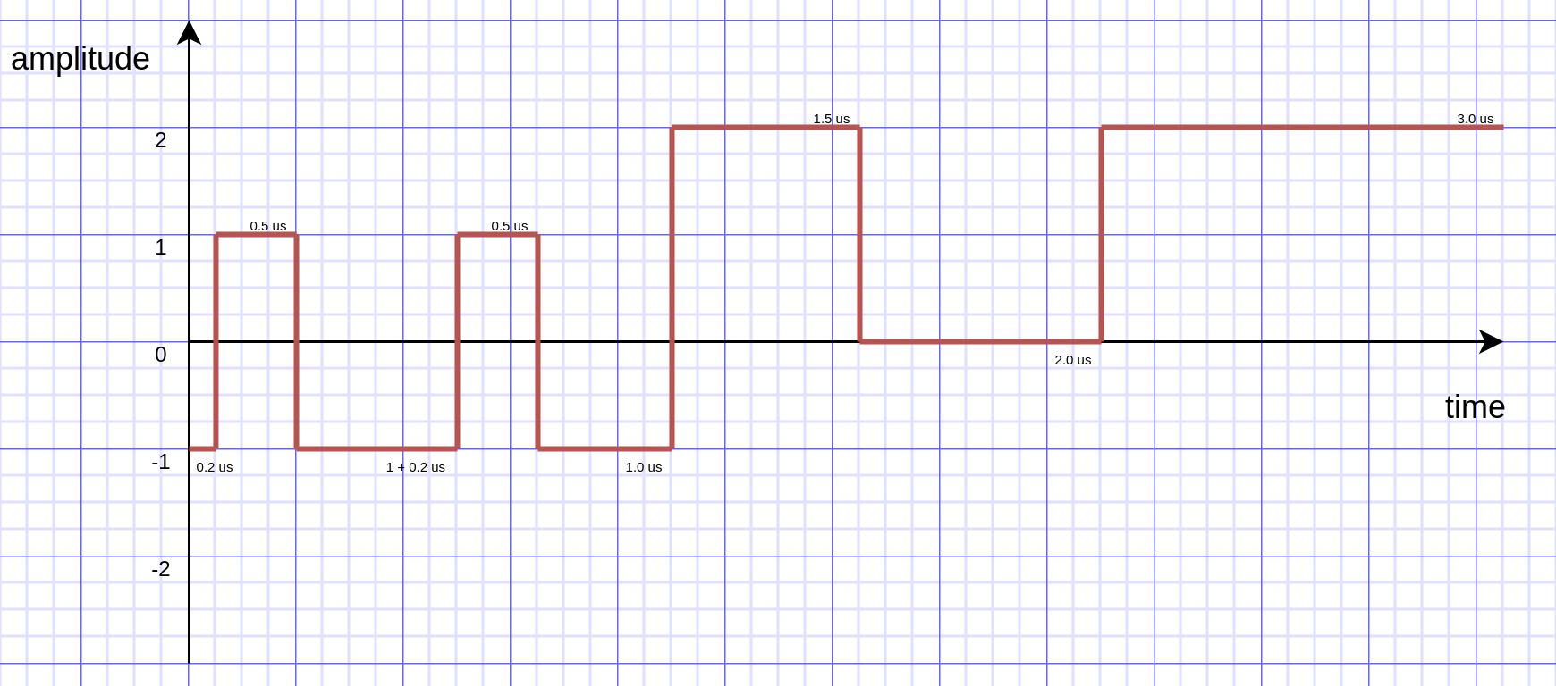
Fig. 2 Example custom TX waveform.
Please also see the CustomTxWaveform.cpp example.
us4r->setVoltage({HVVoltage(5, 6), HVVoltage(10, 11)});

WaveformBuilder waveformBuilder{};

// Set states -1 (0.2 us), 1 (0.5 us), -1 (1 us), and repeat that twice.
waveformBuilder.add(
   WaveformSegment {
       {0.2e-6f, 0.5e-6f, 1e-6f}, // durations
       {-1,      1,       -1}     // states (levels)
   },
   2 // how many times to repeat this segment
);
// Set states 2 (1.5 us), 0 (2 us), 2 (3 us), run it only once (n repeats = 1).
waveformBuilder.add(
   WaveformSegment {
       {1.5e-6f, 2e-6f, 3e-6f}, // durations
       {2,      0,   2}         // states (levels)
   }
);
auto waveform = waveformBuilder.build();
Tx tx{aperture, delays, waveform};