2. Hardware description
2.1. System Overview
The us4R™ system is an ultrasound research device designed for transmission and acquisition of ultrasound signals using connected piezoceramic probes/transducers (use with pMUT/cMUT is feasible but may require a dedicated circuitry – please consult us4us).
The us4R™ is a peripheral device, so in addition to an ultrasound probe, it always requires an external Host PC to work.
The us4R-lite™ is connected using PCIe cables (Fig. 2.1) to a PC running ARRUS™ SDK. An open-source ARRUS™ SDK (Software Development Kit) is provided to be installed and run on the host PC to execute User’s applications/scripting for device configuration, data acquisition, and custom processing.
The ready to use setup consists of the us4R™ device, a host PC computer (Fig. 2.1), an LCD monitor and a set of cables.
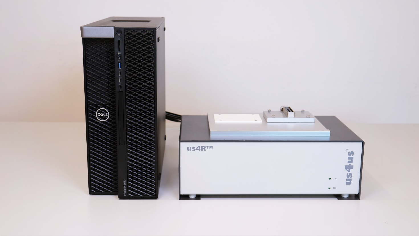
Fig. 2.1 View of the us4R™ connected to the host PC.
As standard, a host PC, an LCD monitor and ultrasound probes are not provided by the Manufacturer.
2.2. Hardware Models
The table below summarizes all hardware models of the us4R™:
Model |
Options |
External Interface |
|---|---|---|
R-2021 (EOL) |
128RX, 192RX, 256RX |
PCIe (4x or 8x gen3 4 lanes) |
R-2023 |
128RX, 192RX, 256RX |
PCIe (4x or 8x gen3 4 lanes) |
2.3. Ultrasound Probe Adapters
The us4R™ research system features changeable ultrasound probe adapter. Depending on the configuration, it can be equipped with an adapter supporting either a single ultrasound probe with up to 1024 elements or two probes (linear/phase/convex) with 256 elements each. Two connectors (CONN #0 and CONN #1) are situated at the top of the device; For matrix-array probe, an dedicated probe adapter is available with 4x DLM6-360 connectors. Only a single probe (linear/phase/convex) probe connector is active at a time. An active probe is used to transmit and receive ultrasound signals that are acquired and processed by the system. The active connector/probe is chosen in software.
Several adapters are available for use with the us4R™ system. Please consult the list of adapters as shown below:
Options * |
Probes compatibility |
Probe adapter specific pinouts |
|---|---|---|
128 RX (4xus4OEM) |
up to 128-element probes (linear/array/convex) |
|
192 RX (6xus4OEM) |
up to 192-element probes (linear/array/convex) |
|
256 RX (8xus4OEM) |
up to 256-element probes (linear/array/convex) and up to 1024-element matrix-array probes |
|
* Switching between 4x, 6x and 8x us4OEM module options can be done by the Manufacturer only.
** Not easily interchangeable! If you plan to use probes above 128 elements from various manufacturers (e.g. Esaote and Philips probes) please contact us4us to find the best solution for you.
Depends on connector type, we offer the following adapters:
Part Number Scheme |
Connector |
Specific pinout |
Rev |
Supported Probes |
List of tested probes |
|---|---|---|---|---|---|
QLC-260-1-EPA |
QLC-260 |
EPA |
3.0 |
ESAOTE compatible |
|
QLC-260-1-DRAM |
QLC-260 |
DRAM |
0.1 |
Draminski compatible |
|
DL1-156-1-PAU |
DL1-156 |
PAU |
1.0 |
ULTRASONIX compatible |
|
DL5-260-1-VPA |
DL5-260 |
VPA |
1.0 |
ATL / Philips compatible |
|
DLP-408-1-HYPGE |
DLP-408 |
HYPGE / RCAV |
2.0 |
GE compatible |
|
SEAF-4-3Dto2D |
SEAF |
3Dto2D |
2.0 |
us4us 2D probe adapters compatible |
|
DL6-360-4-MAT2732 |
DL6-360 |
MAT-2732 |
0.1 |
2D MATRIX 2372 Vermon probe compatible |
|
BTB-MEZ-8-VER |
BTB-MEZ |
VER |
0.1 |
multi-element probe compatible |
|
Probe Adapter Part Number Scheme
To ensure clear identification and compatibility, all probe adapters for the us4R™ system follow a standardized coding system:
ZZZ(Z)-ZZZ(Z) – Connector Type
Y – Number of connectors
XXX(XXXXX) – Specific connector pinout
Connector Type (ZZZ(Z)-ZZZ(Z)) Defines the mechanical connector type used in the adapter (e.g., QLC-260, DL1-156).
Number of connectors (Y) Indicates how many connectors are implemented in the adapter.
Pinout Specification (XXX(XXXXX)) Identifies the detailed pinout configuration or mapping of the adapter, ensuring probe compatibility with the us4R™ system.
This convention allows users to quickly determine the connector type, number of connectors, and probe compatibility. Only adapters that follow this coding scheme and are supplied or approved by us4us® should be used to maintain functional compatibility and safety compliance with IEC 61010-1.
If you cannot find the adapter that suits your application, it is possible to order a custom probe adapter from the us4us®. Please contact us at support@us4us.eu to discuss the options.
Note
The system is supplied with one selected probe adapter. Additional adapters can be purchased separately.
2.4. Inputs and outputs
The us4R™ is equipped with:
up to 2 or 4 probe connectors (depends on the probe adapter installed),
4x or 8x PCIe ports (see Fig. 2.2),
2x digital inputs,
2x digital outputs,
1x IEC mains power input.
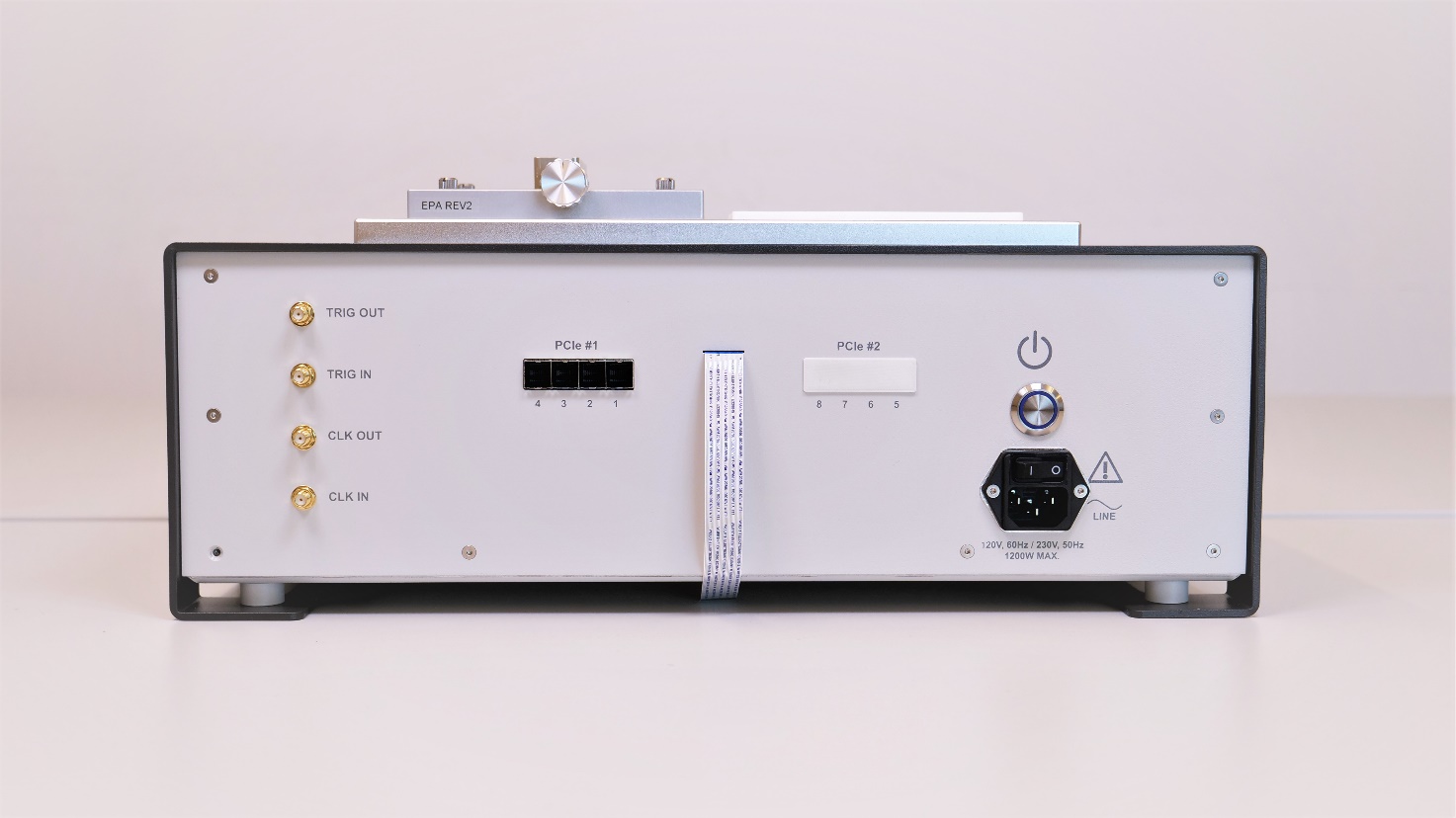
Fig. 2.2 Back-side of the us4R™ device.
PLEASE NOTE: External devices should be connected via cables no longer than 3m.
2.5. Power switch, cable and ON/OFF button
The power cable connection is shown in the picture below (Fig. 2.3).
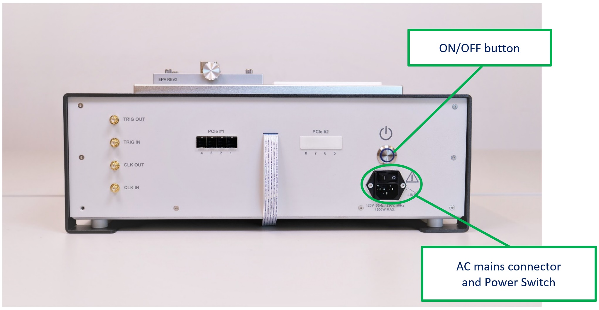
Fig. 2.3 The us4R™ AC power connector and ON/OFF button.
2.6. Connecting ultrasound probes
Ultrasound probes require special care, as they can be easily damaged by an impact. The damaged transducers could have internal element short-circuits or open-circuits, both can cause malfunction or even breakdown of the us4R™ transmit circuitry. Therefore, it is vital that the probes are handled with extreme care and defective probes are never connected to the system.
Probes should be disconnected from the device during the transport.
The ultrasound probe connectors are situated at the top of the device. 2D probes (linear/phase/convex) connectors are marked as CONN #0 and CONN #1 on the figure below.
Please refer to section Section 2.3 for other probe adapters options.
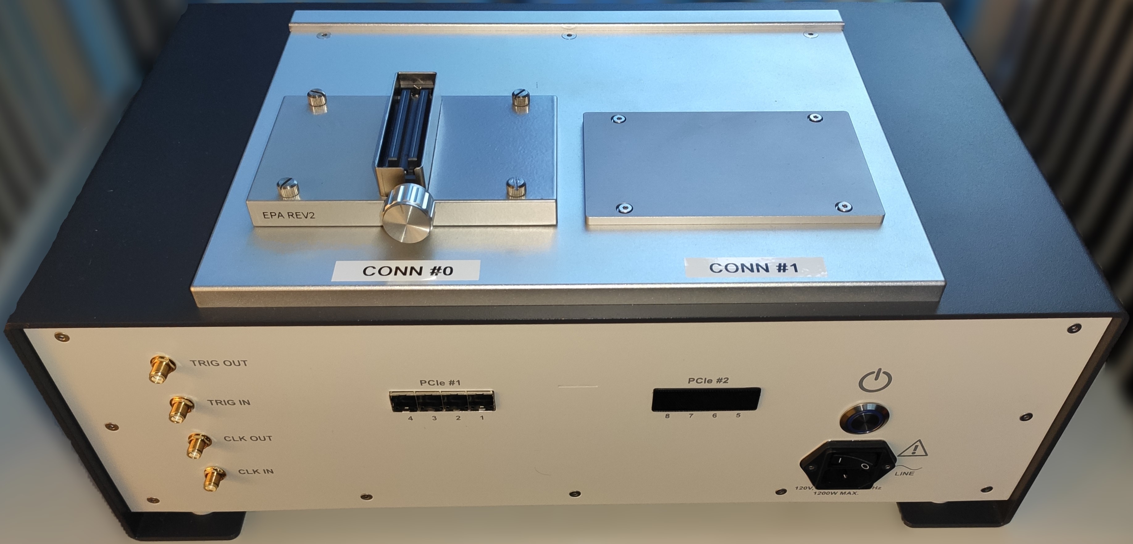
Fig. 2.4 Top-view of the us4R™ with 2D (linear/phase/convex) CONN #0 and CONN #1 connectors.
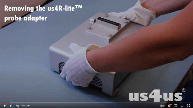
A video instruction on how to change the probe adapter for 2D (linear/phase/convex) probes is available on our YouTube channel:
PLEASE NOTE: Only a probe prepared and configured for use with the us4R™ can be connected to the device. For assistance, please contact the Manufacturer.
Caution
Using non-compatible or broken probes can result in damage to the transmission section of the us4R-lite™! Such damages are NOT covered under the warranty!
Caution
Possibility of electric shock; Probe connectors are hazardous live terminals. Use only with designated ultrasound probes. Do not touch connectors during operation.
2.7. PCIe ports
The us4R™ is equipped with 4 or 8 PCIe ports on the back of the device.
The PCIe ports are intended for connecting the system to an external host PC using dedicated PCIe cables. The us4R™ is provided with compatible host PCIe adapter card(s) that should be properly installed in the host PC controller before first use. For the PXH832 PCIe adapter cards follow the instructions available here
PCIe Ports – Safety Information The PCIe ports of the us4R™ are low-voltage communication interfaces (SELV) intended exclusively for connection to a compatible host PC through the supplied PCIe cables and adapter card(s). Although the PCIe interface itself operates at safety extra-low voltages (3.3V, 12V - internal, LVDS signals), connection is permitted only to a host PC that provides at least the same protection against electric shock as the us4R™ (minimum: Class I, protective earth).
Do not connect the PCIe ports to any device other than the dedicated host PC with the supplied PCIe adapter. Do not attempt to modify or access the PCIe connectors while the system is powered.
2.7.1. Connecting the PCIe cables
The delivered PCIe cables are marked #1 to #4 or #8, to help with proper connection of the us4R™ ports numbered 1…4 or 1…8 to the corresponding ports on the host PC side – also numbered. The proper order of the PCIe cables is essential for device operation and cannot be changed!
When connecting the PCIe cables you should hear/feel “a click” to be sure that the connector is latched properly (Fig. 2.5).
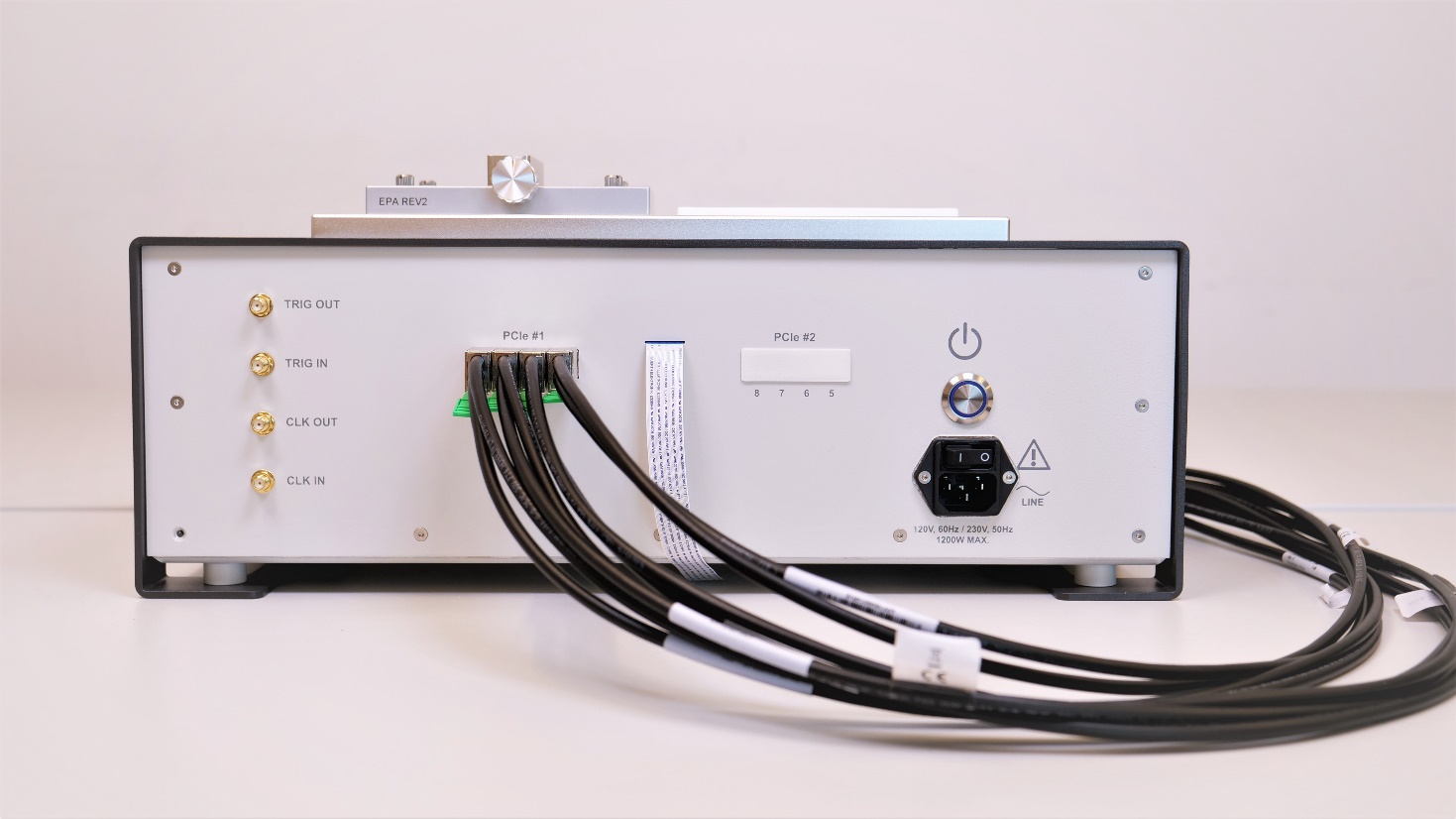
Fig. 2.5 Back panel of the us4R™ showing the PCIe connectors and properly connected cabling.
2.7.2. Connecting host PC & display
The us4R™ requires an external host PC with an LCD monitor to function correctly. The only way to connect the us4R™ device to the PC is through the PCIe cables.
The host PC must be equipped with one or two PCIe adapter cards. Example of the host PC with two PCIe adapter cards installed – one at the top, one at the bottom of the enclosure (Fig. 2.6).
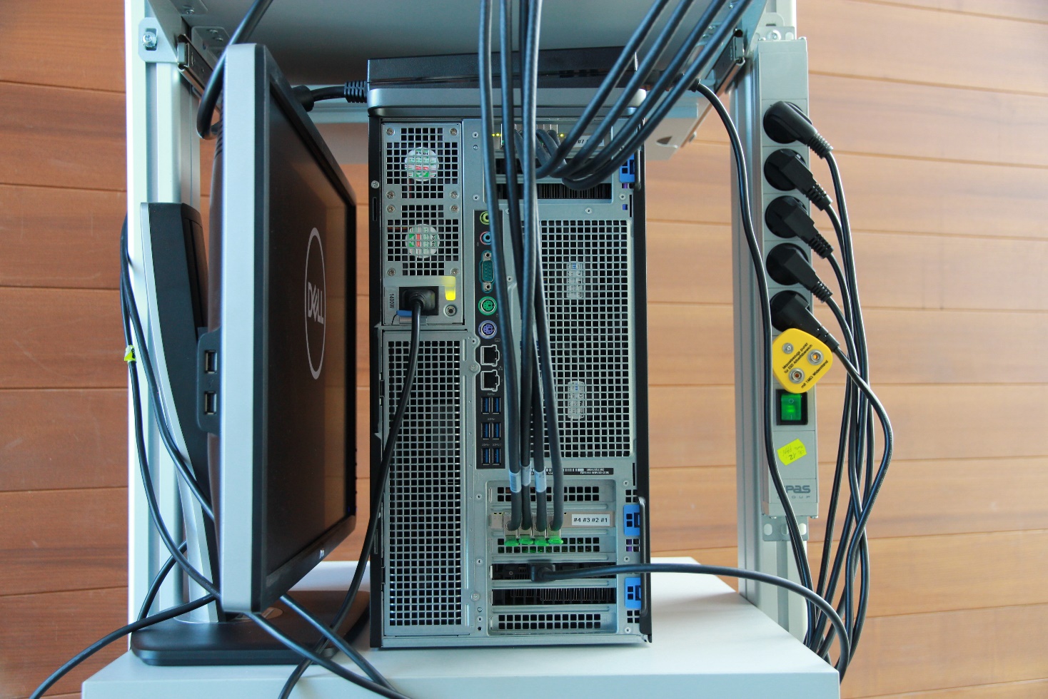
Fig. 2.6 Back-side view of the host PC showing cables connection with two PCIe adapter cards installed.
To disconnect PCIe cables pull the green tab at the bottom of the PCIe cable plug (Fig. 2.7).
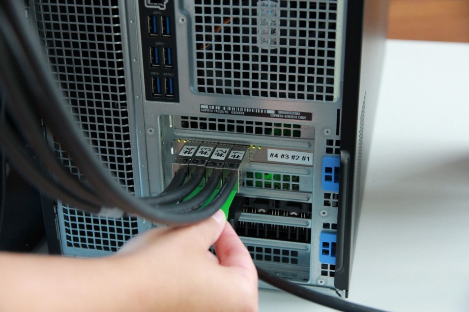
Fig. 2.7 The host PC: the PCIe cables #1…#4 connected to the bottom PCIe interface card. Disconnect by pulling the green tab.
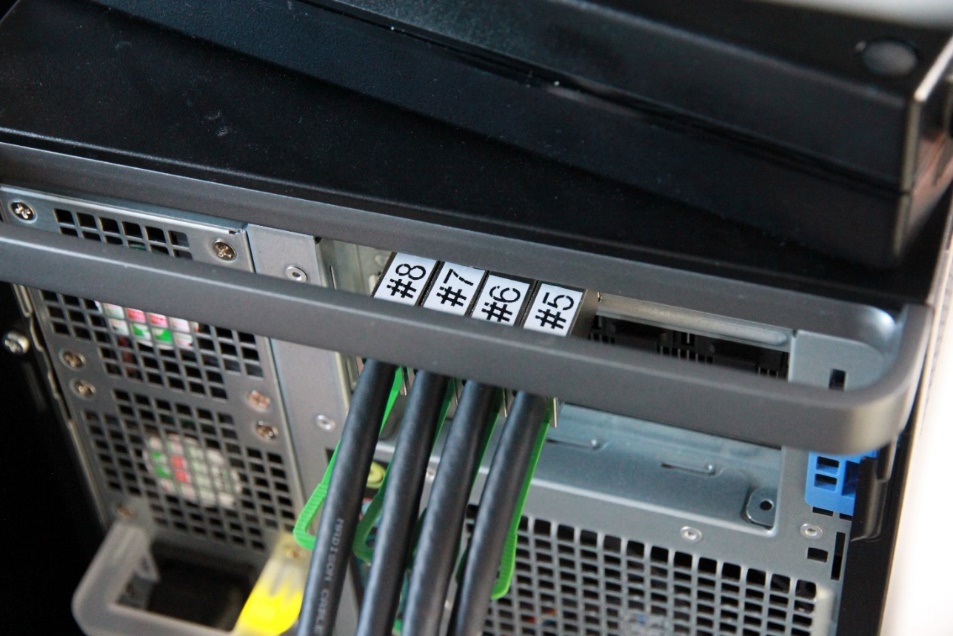
Fig. 2.8 The host PC: the PCIe cables #5…#8 connected to the top PCIe interface card.
Safety and compatibility requirements: To ensure safe and compliant operation, the following requirements apply when connecting the us4R™ to an external PC:
the host PC must provide at least the same level of protection against electric shock as the us4R™ system, i.e., Class I (with protective earth connection) according to IEC 61010-1,
class II equipment (with double or reinforced insulation) is acceptable only if explicitly assessed and approved by the system integrator.
2.8. Digital I/O ports
The us4R™ provides four digital I/O signals in the LVTTL 3.3V standard available on the SMA-type connectors:
CLOCK IN – input of an external reference clock signal.
TRIG IN – input of an external trigger signal – can be used to synchronize transmit events with other devices/systems.
CLOCK OUT – output of an internal reference clock signal.
TRIG OUT – output of an internal trigger signal – can be used to synchronize other external devices/systems with the us4R™.
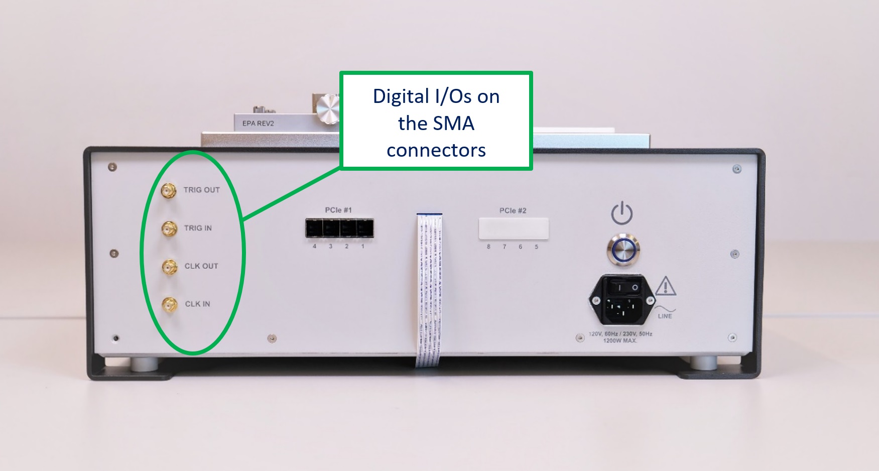
Fig. 2.9 Back panel of the us4R™ showing the 4x digitial I/O signals
Safety note: The digital I/O signals (CLOCK IN, TRIG IN, CLOCK OUT, TRIG OUT) are classified as SELV (Safety Extra Low Voltage) circuits and operate at 3.3 V LVTTL logic levels. These connectors shall be connected only to equipment that provides SELV-compatible signals and meets at least the same protection against electric shock as the us4R™ (minimum: Class I). Applying voltages outside the specified 0–3.3 V range may damage the device and void compliance with IEC 61010-1.
Do not connect these ports to mains-powered circuits, industrial I/O, or non-SELV signals.