Examples
In the following parts of this chapter, we will show you how to run example scripts available in the ARRUS software. The source code of the ready-to-run examples can be found in python/examples directory.
For more information on the parameters of individual functions please refer to section API Reference.
For the user guide and all the assumptions (e.g. about the coordinate system) please visit sections Glossary and assumptions and User Guide.
Before running any of the below examples:
Make sure you are running the Python script using the appropriate Python distribution; please install python/examples/requirements.txt file first (if you haven’t already that done).
Make sure you are using correct configuration file. See Running the Scheme for more information how the path to configuration file is determined when creating session object.
Make sure that the correct parameters are set, in particular the transmitting voltage.
Plane Wave Imaging
Go to python/examples directory.
Run
python plane_wave_imaging.py
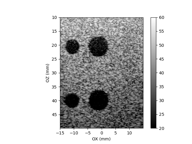
This script implements ‘plane wave imaging’ scheme, where the image is formed by combining a couple low-resolution images into one high-resolution image. Each low-resolution image is formed using data acquired after transmission of a plane wave at a different angle. After starting the script, you should be able to see an output similar to the below one:

Fig. 3 Plane wave imaging python script output. Phantom: ATS549, cysts. Probe: L14-5/38 from Ultrasonix.
Classical Beamforming
Go to python/examples directory.
Run
python classical_beamforming.py
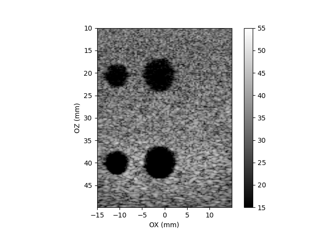
This script implements classical transmit-receive scheme, where the image is formed using line by line scanning. After starting the script, you should be able to see an output image similar to the below one:

Fig. 4 Classical beamforming script output image. Phantom: ATS549, cysts. Probe: L14-5/38 from Ultrasonix.
Diverging Beams
Go to python/examples directory.
Run
python diverging_beams.py
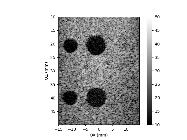
This script implements diverging beams transmit-receive scheme, where the image is formed using data acquired after couple transmissions of diverging beams with different virtual focuses. After starting the script, you should be able to see an output image similar to the below one:

Fig. 5 Diverging beams scheme script output image. Phantom: ATS549, cysts. Probe: L14-5/38 from Ultrasonix.
Others
The /examples directory contain addtional scripts custom_callback.py and custom_tx_rx_sequence.py
which show how to construct custom sequences and callbacks.
Check probe
Sometimes some of the transducers in the probe can be damaged, e.g. mechanically. Such a damaged transducer can be potentially dangerous to the system, e.g. it can cause mismatched current flow in some subsystem and damage it. This example consists of a python script (arrus/api/python/examples/check_probe.py) evaluating transducers in ultrasound probe. The evaluation is made on the basis of values of features estimated from signals acquired by each transducer. The transmit-receive scheme includes transmitting by single transducer and receiving by transducers in aperture centered on the transmitter. It is assumed that there are lens on transducers, and the probe is in the air, thus the analysed signal comes from reflection at the lens-air interface. Each transducer is excited by a short (single period) and low voltage (10V).
Current features
amplitude
pulse duration
energy of normalised signal
- pearson correlation coefficient (PCC) with footprint signal
PCC require a footprint (i.e. object containing reference rf signal array). The footprint should be acquired earlier using the same setup. This feature measure how much the signals changed comparing to footprint. When transducer is broken, the acquired signal should be different comparing to signal acquired before damage.
Methods of evaluation
- Threshold
It bases on the values of features estimated from signals acquired from examined transducer. If the value is outside predefined range, the corresponding transducer is treated as suspected. These ranges can be set in FeatureDescriptor() calls in the main() function of the script (below “# define features list”). This ranges can differs between probes.
- Neighborhood
It bases on the values of features estimated from signals acquired from examined transducer and transducers in close neighborhood. If the value from the examined transducer differs from the values from other transducers by more then arbitrary percentage, the transducer is treated as suspected. Note, that PCC should be validated using threshold method (i.e. usign ByThresholdValidator()).
How to use the script
The script is called from command line with some options. At the end of its run, the scripts (optionally) display figures with values of the features, and initial segments of signals from all transducer, for visual evaluation.
Following options are accepted:
required:
--cfg_path: path to the system's configuration file,
optional:
--help: displays help,
--method: determines which method will be used - 'threshold' (default) or 'neighborhood',
--rf_file: determines the name of optional output file with rf data,
--display_frame: determines if script will display figures for visual evaluation,
--n: the number of full Tx cycles to run (default 8),
--tx_frequency: determines transmit frequency in [Hz] (default 8e6),
--nrx: determines the size of receiving aperture (default 32),
--create_footprint: creates footprint and store it in given pickle file,
--use_footprint: determines which footprint file to use,
--display_summary: displays features values on figure,
--show_pulse_comparison: displays acquired pulse and corresponding footprint signal
--features: features to evaluation (amplitude, energy, duration, pcc)
Examples:
python check_probe.py --help
python check_probe.py --cfg_path /home/user/us4r.prototxt
python check_probe.py --cfg_path /home/user/us4r.prototxt --rf_file rf.pkl
python check_probe.py --cfg_path ~/us4r.prototxt --create_footprint footprint.pkl --n=16
python check_probe.py --cfg_path ~/us4r.prototxt --use_footprint footprint.pkl
python check_probe.py --cfg_path ~/us4r.prototxt --use_footprint footprint.pkl --features amplitude pcc
Additional notes:
1. This script tries to identify channels it considers suspicious. In the case of a suspicious channel, the user should verify it manually (i.e. to look on the signal from the channel and decide, if it is good or not), because the features used are only indicative.
2. Some features (like pulse duration) are more sensitive than the others, i.e. are more likely to give false positives. If there are a lot of false positives one can remove the feature from the list of features to verify.
3. Using of threshold method assume that one know the range of values of verified features. These ranges often are different for different probes. If one do not know the feature range of values, the neighborhood method can be used.
4. The use of probe footprint seems to be the most convenient, however it require to create a footprint (using –create_footprint option). It assume, that all channels are ok during footprint creation, and later it just indentify channels where signals not match with the footprint. Thus, when some channel is damaged during footprint creation, it may be undetected on later tests.
5. Remember to set proper tx_frequency (using –tx_frequency) when create a footprint or making tests without it (when footprint is used, tx/rx scheme parameters will be taken from it).