4. Description and general rules of use
Attention
The device can only be operated by users with a base knowledge of programming and fundamental PC skills. It is essential that users read the full text of the instruction manual before operating the device.
Attention
Before first use, you must ensure that the device is complete and in good condition. Any mechanical damage, spillage stains or similar faults require servicing. Under no circumstances can a faulty or damaged network cable be used.
Attention
Using the us4R™ out of its intended use, or any use that has not been delineated in this manual, will lower the effectiveness of measures put in place to protect the user from danger, and result in a decrease of safety levels.
The ready to use setup consists of the us4R™ device, a host PC computer (Fig. 4.1), an LCD monitor and a set of cables.
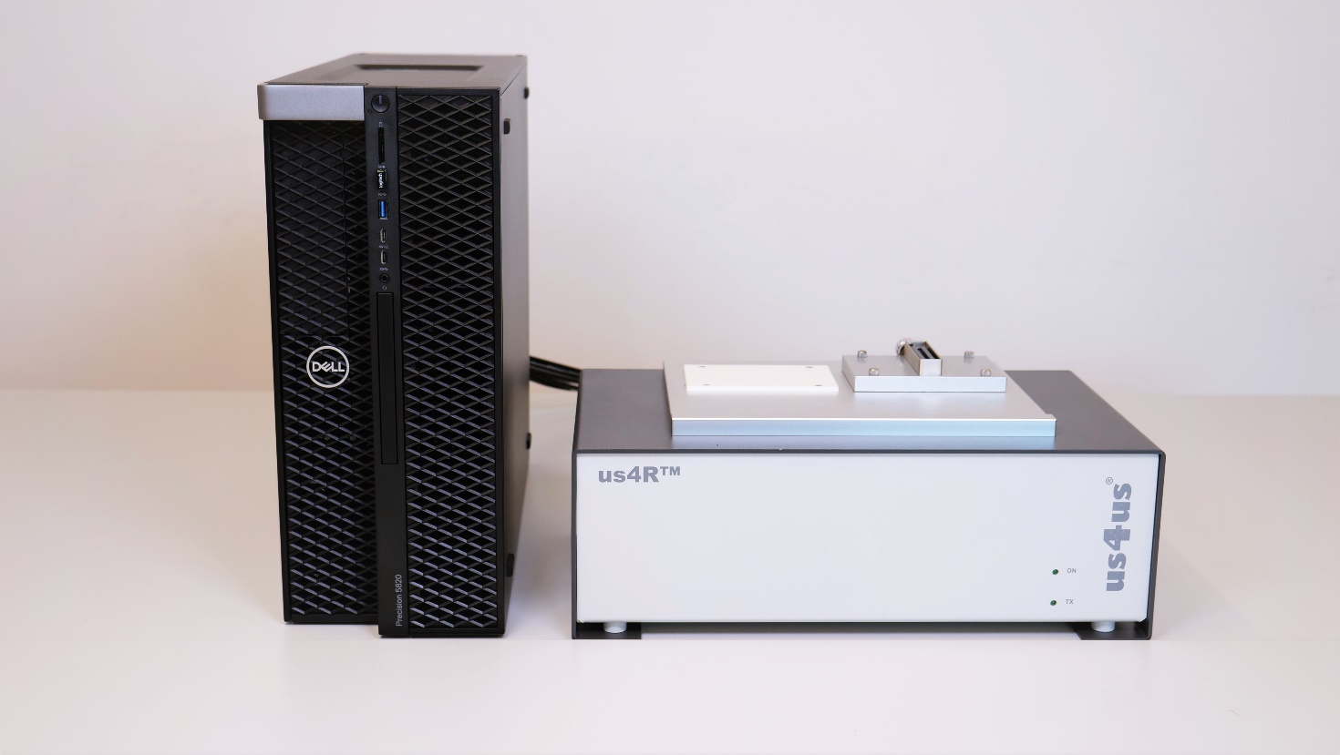
Fig. 4.1 View of the us4R™ connected to the host PC.
As standard, a host PC, an LCD monitor and ultrasound probes are not provided by the Manufacturer.
The us4R™ enables the user to simultaneously connect up to two ultrasound probes (linear/phase/convex). Two connectors (CONN #0 and CONN #1) are situated at the top of the device; For matrix-array probe, an dedicated probe adapter is available with 4x DLM6-360 connectors. Only a single probe (linear/phase/convex) probe connector is active at a time. An active probe is used to transmit and receive ultrasound signals that are acquired and processed by the system.
The active connector/probe is chosen in software.
Ultrasound echo signals from the probe are digitized and transmitted via single/dual PCIe gen3 x16 digital interface to the PC, and then further to the GPU cards. Real-time data processing takes place in the CPU/GPUs.
The processed data can be presented graphically on an LCD monitor.
Caution
Never unplug the probe from the device during transmission! This can result in damage to the transmit section of the us4R™ device!
Attention
The device is not equipped with life functions monitoring or alarm systems. The us4R™ is not designed to monitor life functions!
4.1. Inputs and outputs
The us4R™ is equipped with:
up to 2 or 4 probe connectors (depends on the probe adapter installed),
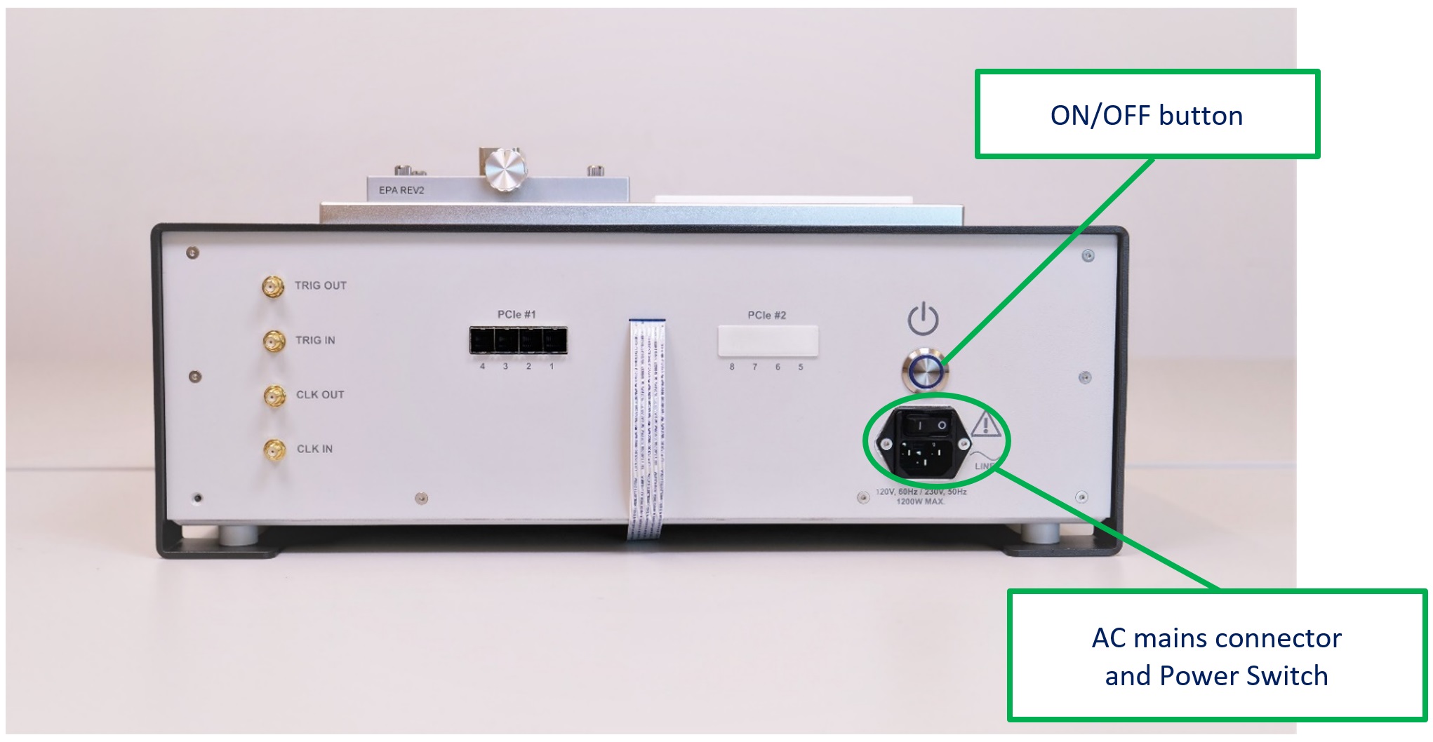
4x or 8x PCIe ports (see Fig. 4.2),
2x digital inputs,
2x digital outputs,
1x IEC mains power input.
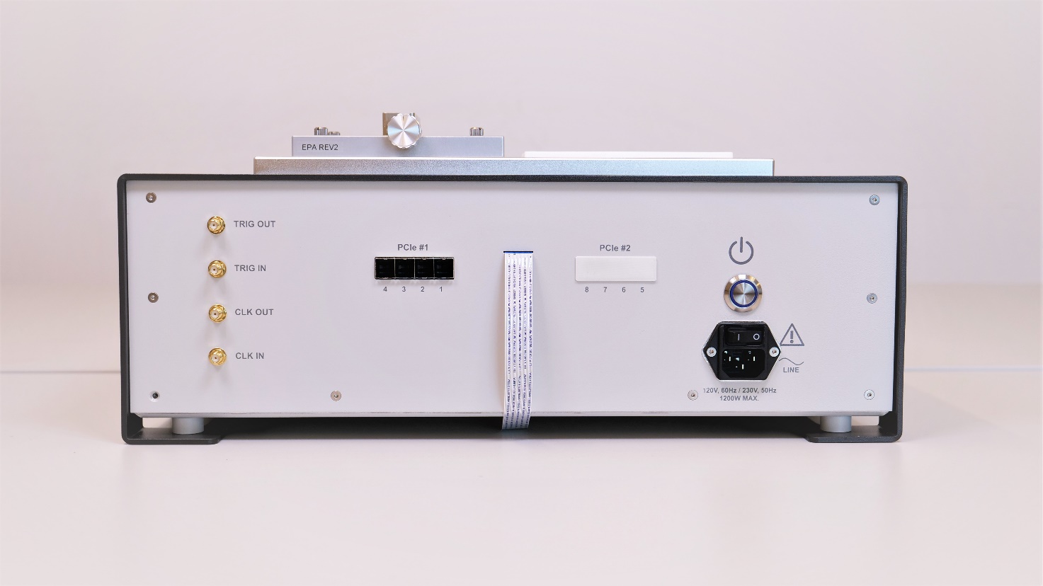
Fig. 4.2 Back-side of the us4R™ device.
PLEASE NOTE: External devices should be connected via cables no longer than 3m.
4.3. Connecting ultrasound probes
Ultrasound probes require special care, as they can be easily damaged by an impact. The damaged transducers could have internal element short-circuits or open-circuits, both can cause malfunction or even breakdown of the us4R™ transmit circuitry. Therefore, it is vital that the probes are handled with extreme care and defective probes are never connected to the system.
Probes should be disconnected from the device during the transport.
The ultrasound probe connectors are situated at the top of the device. 2D probes (linear/phase/convex) connectors are marked as CONN #0 and CONN #1 on the figure below.
Please refer to section Section 3.2 for other probe adapters options.
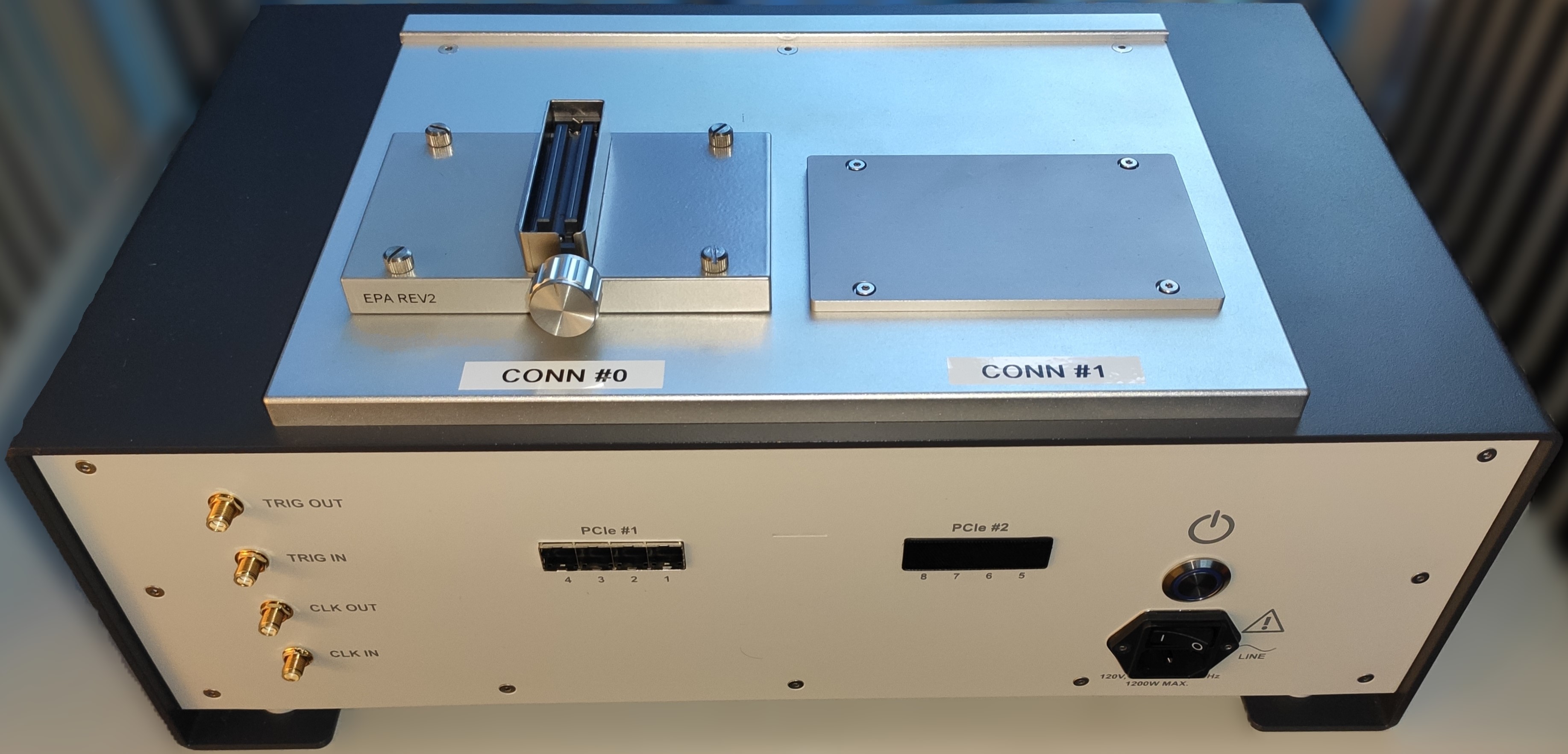
Fig. 4.4 Top-view of the us4R™ with 2D (linear/phase/convex) CONN #0 and CONN #1 connectors.
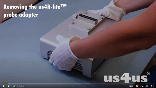
A video instruction on how to change the probe adapter for 2D (linear/phase/convex) probes is available on our YouTube channel:
PLEASE NOTE: Only a probe prepared and configured for use with the us4R™ can be connected to the device. For assistance, please contact the Manufacturer.
Caution
Using non-compatible or broken probes can result in damage to the transmission section of the us4R™! Such damages are NOT covered under the warranty!
4.4. PCIe ports
The us4R™ is equipped with 4 or 8 PCIe ports on the back of the device.
The PCIe ports are intended for connecting the system to an external host PC using dedicated PCIe cables. The us4R™ is provided with compatible host PCIe adapter card(s) that should be properly installed in the host PC controller before first use. For the MXH932 PCIe adapter cards follow the instructions available here
4.4.1. Connecting the PCIe cables
The delivered PCIe cables are marked #1 to #4 or #8, to help with proper connection of the us4R™ ports numbered 1…4 or 1…8 to the corresponding ports on the host PC side – also numbered. The proper order of the PCIe cables is essential for device operation and cannot be changed!
When connecting the PCIe cables you should hear/feel “a click” to be sure that the connector is latched properly (Fig. 4.5).
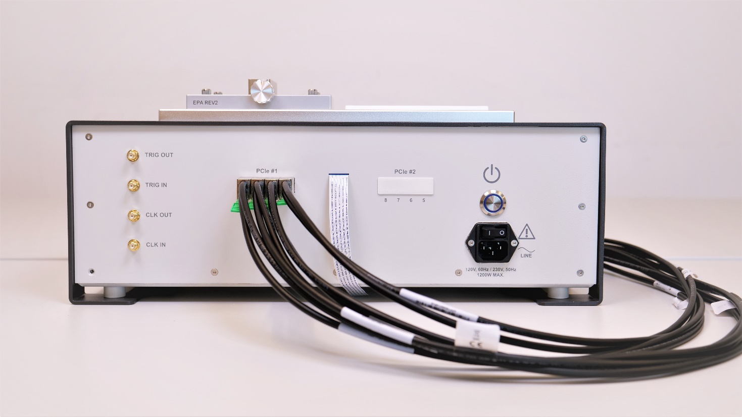
Fig. 4.5 Back panel of the us4R™ showing the PCIe connectors and properly connected cabling.
4.4.2. Connecting host PC & display
The us4R™ requires an external host PC with an LCD monitor to function correctly. The only way to connect the us4R™ device to the PC is through the PCIe cables.
The host PC must be equipped with one or two PCIe adapter cards. Example of the host PC with two PCIe adapter cards installed – one at the top, one at the bottom of the enclosure (Fig. 4.6).
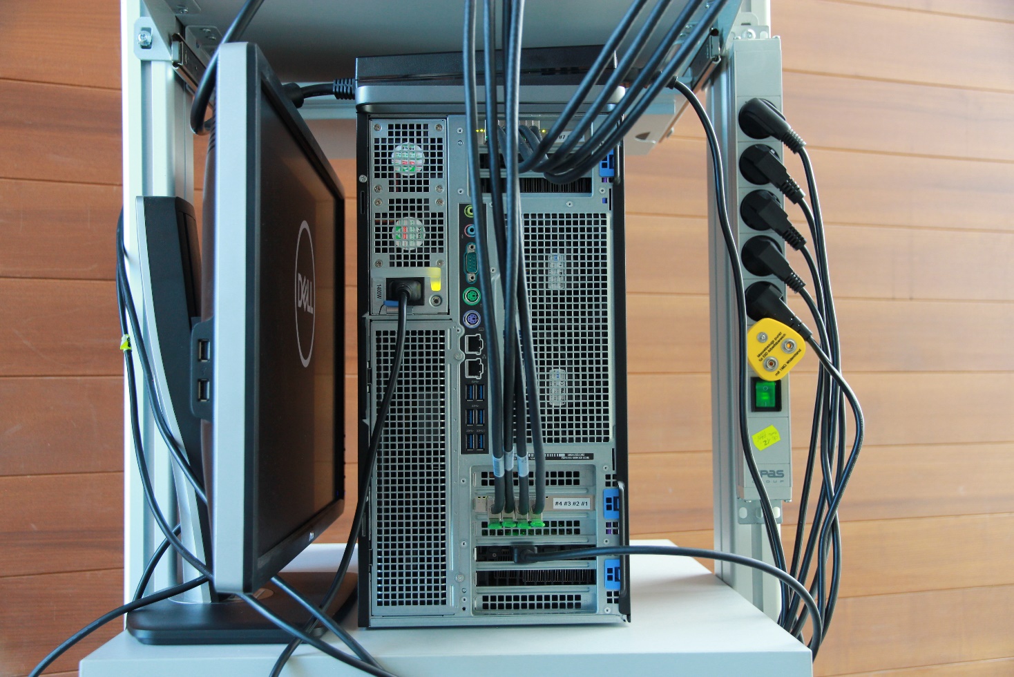
Fig. 4.6 Back-side view of the host PC showing cables connection with two PCIe adapter cards installed.
To disconnect PCIe cables pull the green tab at the bottom of the PCIe cable plug (Fig. 4.7).
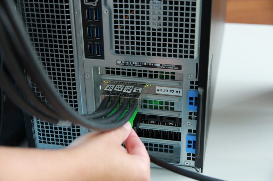
Fig. 4.7 The host PC: the PCIe cables #1…#4 connected to the bottom PCIe interface card. Disconnect by pulling the green tab.
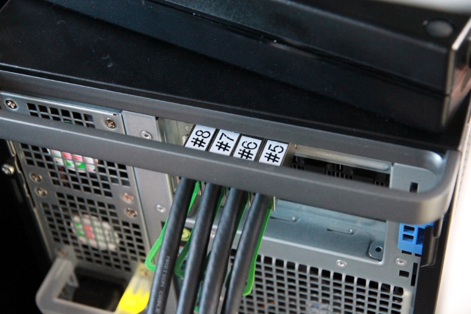
Fig. 4.8 The host PC: the PCIe cables #5…#8 connected to the top PCIe interface card.
4.5. Digital I/O ports
The us4R™ provides four digital I/O signals in the LVTTL 3.3V standard available on the SMA-type connectors:
CLOCK IN – input of an external reference clock signal.
TRIG IN – input of an external trigger signal – can be used to synchronize transmit events with other devices/systems.
CLOCK OUT – output of an internal reference clock signal.
TRIG OUT – output of an internal trigger signal – can be used to synchronize other external devices/systems with the us4R™.
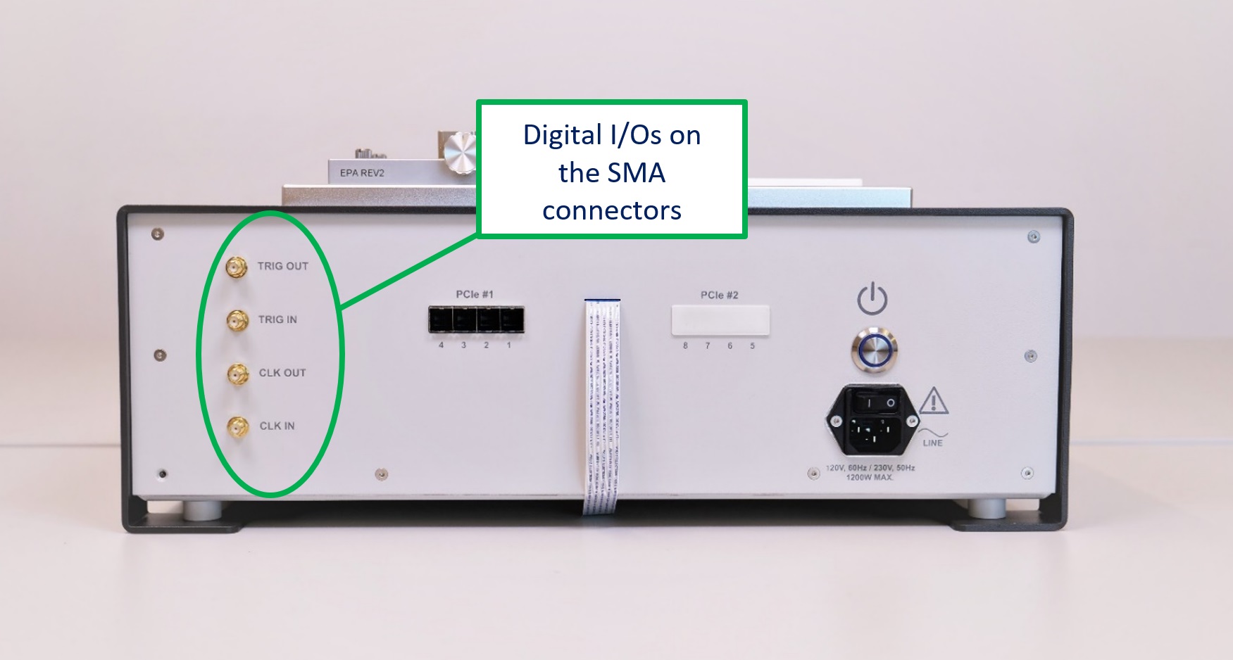
Fig. 4.9 Back panel of the us4R™ showing the 4x digitial I/O signals
4.6. Setting High-Voltage (HV) supply for the transmitters
Caution
Voltages above 70VDC constitute a life hazard according to EN 61010-1 and great care must be takes when using the power supply at voltages above this level!
The system TX voltage (so called HV – High Voltage) is one of the most crucial parameters from the system/probe safety point of view. Because the us4R™ is a research system, it enables the user to change many TX parameters (TX scheme, PRF, TX voltage, pulse length, etc.). However, some combinations of the TX parameters can be dangerous for the connected ultrasound probe and/or the system itself! Therefore, the user is fully responsible for verifying a safe set of TX parameters that can be used with the connected probe in a given application. Application of an excessive TX voltage or power to the probe can (will) result in damage to the system and/or the probe!
We strongly advise to use the lowest TX voltage possible – as low as reasonably achievable (ALARA rule). Also, please consult us4us® and the probe producer to get advice on the max TX voltage and power that can be delivered to the probe.
