Connecting external Trigger Input
In this document we present instructions on how to connect and use an external trigger generator with the us4us ultrasound systems.
This document describes ARRUS-Toolkit example: common/trigger_input
Intended use
The instruction and example provided here can be applied for whatever application it is necessary to synchronize the ultrasound system with an external trigger signal, such as: photo-acoustic imaging, externally controlled transmissions, etc.
The example described here provides access to the raw channel data (RF).
Requirements
Hardware:
us4R-lite+ system
General-purpose signal generator
Software:
ARRUS Python >= 0.11.0
gui4us >= 0.3.0-dev20241008
Installation
Hardware:
Connect the signal generator output to the ultrasound system “TRIG IN” port.
Connect the ultrasound system “CLK OUT” port to the signal generator clock input.
Software:
Download the trigger_input example (the whole directory).
Update the
us4r.prototxt: set the proper probe adapter name, probe name, HV model name.
Parameters
General-purpose signal generator
Caution
When a high frequency value is used (>= 100 Hz), we recommend setting the n_frames value also sufficiently high (e.g. 100 frames for 100 Hz) to mitigate the overhead caused by starting and stopping the transfer via the interface between the system and the host PC.
See also the Python scripts section for more information.
Name |
Value |
|---|---|
Frequency |
In accordance with user requirements (max 10 kHz). |
Amplitude |
|
Waveform |
Pulse |
Pulse Width |
10 us |
Rise edge |
~ 9 ns |
Load |
Python scripts
The below parameters can be changed in the common/trigger_input/env.py
script file, in the section e.g.:
# ------------ PARAMETERS
n_samples = 2048
n_frames = 100
tx_aperture = [True]*n_elements
tx_delays = np.sum(tx_aperture)
# -------------
Name |
Description |
|---|---|
n_frames |
Number of logical frames to be acquired in a single data transfer. One logical frame may be translated into multiple physical TX/RX operations, depending on the number of elements in your transducer and the number of RX channels available in the ultrasonic system. For example, if 128 elements of the probe are used in RX on the system with 64 RX channels, the observed frame rate will be halved. This value should be selected according to the chosen signal generator frequency. When high frequency values are used (>= 100 Hz), we recommend setting the number of frames also sufficiently high to mitigate the overhead caused by starting and stopping the transfer via the interface between the system and the host PC. |
tx_aperture |
TX aperture definition. The TX aperture should be defined as boolean array (mask) for selected probe elements to be used in TX. For the photo-acoustic application, please consider setting this value to |
n_samples |
Number of samples to acquire in a single RX (RF frame). This value determines imaging maximum depth. |
We also encourage you to modify other parameters of the TX/RX sequence in the env.py file. For more information, please refer to the documentation for your version of ARRUS.
How to run
Turn on the appropriate output of the signal generator.
Start the example, please execute the following command in the terminal:
gui4us --cfg /path/to/examples/common/trigger_input
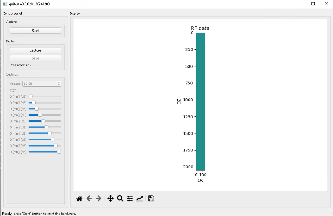
After successfully launching the application, a window like the one below should appear.

Press Start button.
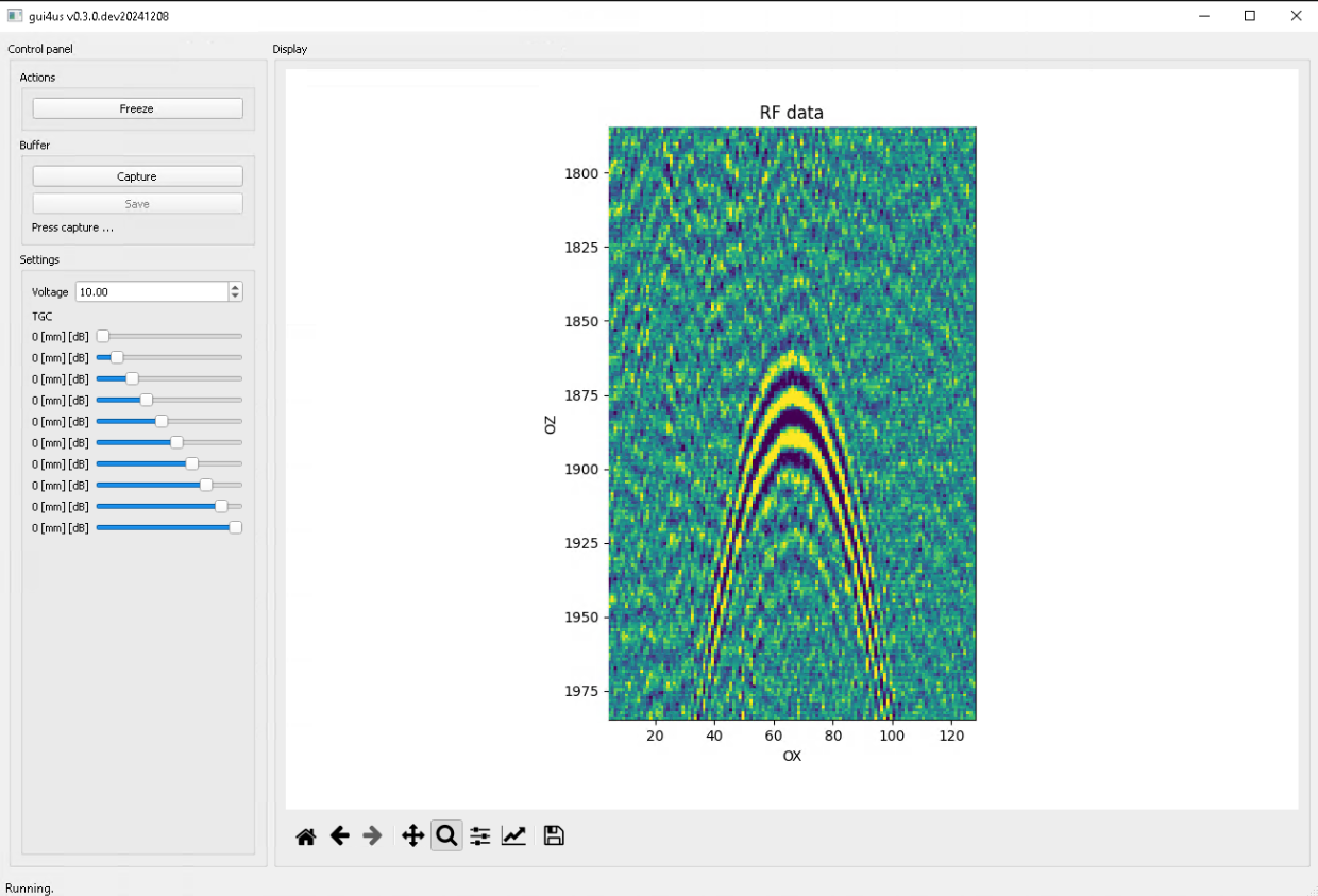
After running the example, the presented RF data should be updated with the frame according to the frequency set on the generator.

You can acquire data by pressing Capture button, then by pressing Save.
The data will be saved in the current working directory (i.e. the currently
visited folder in the terminal).
To stop the TX/RX sequence, please close the GUI4us window.
Utils
The analyse.ipynb notebook shows how to read the data acquired using
the gui4us capture buffer.